Vector Circuit analyzers in modern electronics
Vector circuit analyzers (VAC) have become an essential tool in the arsenal of electronics engineers involved in the design, development and testing of high-frequency devices and components. From modest RF circuits to complex microwave systems, VAC provides unprecedented precision and detail in analyzing the characteristics of electrical circuits in the frequency domain. Their role in optimizing parameters, troubleshooting, and ensuring compliance with the requirements of ever-increasing standards is becoming increasingly critical.
Operating principles and basic parameters
The operation of the VAC is based on the principle of measuring the complex coefficient of signal transmission through the circuit under study (Device Under Test, DUT). This means that the VAC measures not only the amplitude of the transmitted signal, but also its phase relative to the original signal. Based on these data, the parameters of the S-matrix (scattering parameters) are calculated, which comprehensively describe the behavior of DUT at various frequencies. S-parameters such as S11 (input reflection coefficient), S21 (input-to-output transmission coefficient), S12 and S22 allow you to get a complete picture of the circuit characteristics, including its alignment with the source and load, gain, loss and phase distortion.
The key parameters that determine the performance of the VAC include:
- Frequency range: Defines the maximum and minimum frequencies at which the VAC can perform measurements. Modern VATS are capable of operating in the range from several Hz to hundreds of GHz, covering a wide range of applications.
- Dynamic range: Reflects the ability of the VAC to measure both weak and strong signals. The large dynamic range makes it possible to analyze circuits with a high degree of attenuation or gain.
- Accuracy: Characterizes the measurement error caused by various factors such as temperature instability, noise, and calibration errors.
- Measurement speed: Determines how fast the VAC can measure the S-parameters at each frequency. Faster measurement speeds can reduce testing time and increase productivity.
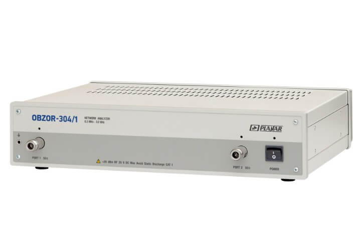
- Number of ports: Defines the number of inputs and outputs to which the DUT can be connected. VAC with multiple ports allows you to analyze complex multi-pole devices.
Architecture and functionality
A typical VAC consists of the following main components:
- Signal source: Generates a test signal that is applied to the DUT.
- Signal Separator: Divides the signal into two paths: one for feeding to the DUT and the other for the reference signal.
- Receivers: