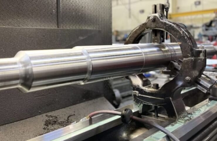
A long non—rigid shaft is a classic turner's headache. The part "sings", a characteristic ripple appears on the surface, and when measured, it turns out that the diameter in the middle is larger than at the edges. They try to reduce the flow, but it doesn't help. Changing the plate is the same thing.
Let's figure out what's really going on.
The main parameter is the L/D ratio
The stiffness of a shaft is determined by the ratio of its length to its diameter. Indicative recommendations:
- L/D up to 3-4 — can be cantilevered in the chuck;
- L/D from 4 to 10 — preload is mandatory with the rear center;
- L/D is more than 10-12 — you need a lunette (fixed or movable).
These are guidelines, not rigid rules: a lot depends on the material, the required accuracy and modes.
Why does the "barrel" appear?
When turning, the cutting force acts on the workpiece, which is decomposed into three components. The radial component Py is important for rigidity — it pushes the part away from the cutter. The shaft, fixed in the chuck and in the center, bends most strongly in the middle. The cutter removes less metal where the part has "gone", and a barrel shape is obtained.
With cantilever fastening, the picture is different: the deflection is maximal at the free end, a taper is obtained.
Where do the vibrations come from
There are forced fluctuations (from imbalance, drive malfunction, intermittent cutting) and self-oscillations. It is self—oscillation that is the main problem when turning non-rigid parts. The cutter leaves a wavy trail, on the next revolution the chip thickness changes, the cutting force fluctuates, the vibrations are fueled and increase. This is the so-called regenerative effect.
What to do: tool geometry
- The main angle in the plan is close to 90° (93-95°). The radial component of the cutting force decreases, the main load goes along the shaft axis.
- Small radius at the top. On the finishing passages — 0.2–0.4 mm. A large radius increases the radial force.
- Sharp positive geometry. Plates with a positive front angle and a sharp edge cut "easier".
- The correct chip breaker for the selected depth and feed.
What to do: cutting modes
- Reduce the cutting depth, not just the feed. The depth has a stronger effect on the radial load.
- Change the speed. Sometimes it helps to get out of the resonant zone, both up and down. It is worth trying to change the speed by 10-20%.
- Do not operate with too low a feed. If the feed is less than the radius of the rounded edge, the tool begins to rub rather than cut, which also causes vibration.
What to do: billet support
The back center. A rotating one is better. The preload force is moderate: the overstretched center bends itself